METRICON MODEL 2010/M PRISM COUPLER -- APPLICATION NOTE 105 (2/16)
CHARACTERIZATION OF OPTICAL WAVEGUIDES/WAVEGUIDE LOSS
With Metricon’s Model 2010/M, waveguide characterization data which typically requires a skilled professional an hour or more to collect with homemade apparatus can now be obtained in 30 seconds or less in a format providing complete documentation of results and measurement conditions. Thickness and index of the guiding layer (and very often the cladding layer) are easily measured for planar layers, as are the number of modes and effective mode indices and options 2010-WGL1 and 2010WGL2 permit measurement of waveguide loss.
Characterization of guiding layer thickness and index, cladding layer, number of modes and mode indices
For all types of planar guides, the Model 2010/M provides rapid measurement of mode indices, and for step index guides, calculation of guide thickness and refractive index and, in most cases, substrate or cladding index. In addition, with the standard TE-mode measurement, indices for both guides and substrate materials are measurable along any in-plane direction, while the TM option provides measurement in the perpendicular-plane direction.
For graded index guides, an index vs depth calculation based on the method of Chiang (J. Lightwave Technology, LT-3, p. 385, April 1985) is provided (see sample lithium niobate waveguide calculation below). A mode modeling feature is also provided which permits calculation of mode angles and effective indices from single and dual film thickness and index values input by the user.
Until recently, waveguide characterization with the 2010/M has been limited to planar waveguides, but two recent papers (B. Chen et al, IEEE Phot. J., 4(5), 1553-1559 (October 2012) and K. S. Chiang et al, Opt. Engr., 47(3), 034601-1 to 034601-4 (March 2008)) have shown the feasibility of using the 2010/M to measure effective mode indices for arrays of stripe and channel waveguides.
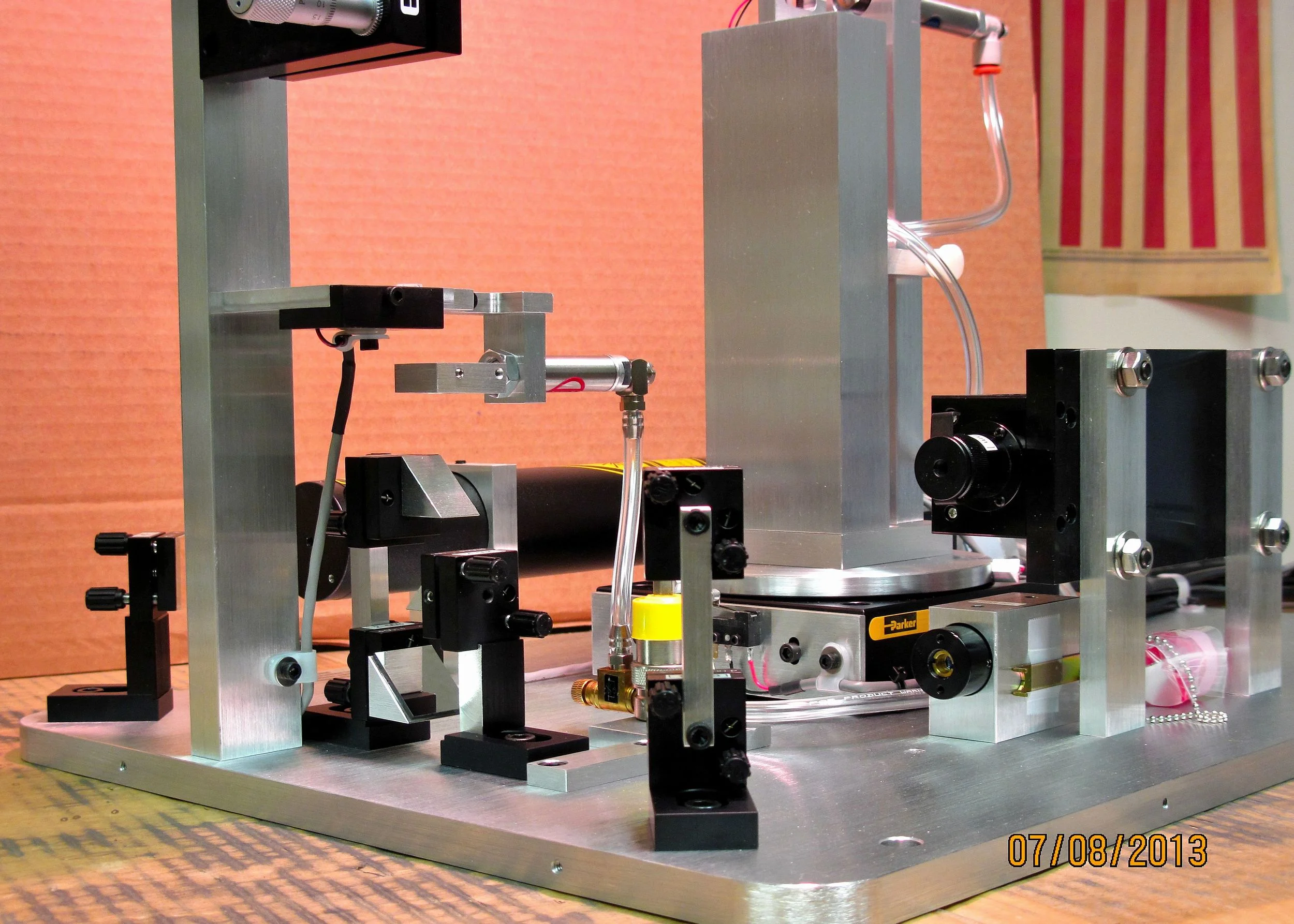
Major components of the Model 2010/M include: a coupling mechanism which brings the waveguide and the prism into intimate contact in a gentle and reproducible fashion; a laser and a step motor-driven rotary table to vary the angle of incidence of the beam on the prism; and a PC-based controller which employs pattern recognition software to determine effective mode indices (and resulting thickness and index) from the pattern of beam intensity reflected from the base of the prism vs. incident angle. All aspects of system operation, including table positioning and detection of modes, can be performed fully automatically or manually by the user.
Further features of interest for integrated optics work include:
Operating wavelength: Although the standard system operates at 633 nm, most systems for integrated optics provide one or two additional beamlines so that multiple lasers can be used with the system. The Model 2010/M can be supplied with additional lasers in the 400-1600 nm range, or the system can be configured with a port for a user-supplied laser external to the system. For such multiple beamline systems, wavelength selection consists simply of opening and closing the appropriate mechanical beam blocks and changeover between wavelengths requires 10 seconds or less. Popular wavelengths for optical waveguide measurements include 830, 1310 and 1550 nm. In addition, we have configured systems with 405, 450, 473, 520, 532, 650, 780, 850, 980, and 1064 nm lasers.
Resolution/accuracy: A high resolution rotary table with software‑selectable angular resolution of 0.9 or 0.45 minutes is usually ordered as a no-cost option for waveguiding applications. For this table, effective index (β-value) resolution is .0002 (".0001) with 0.9 minute operation and .0001 (".00005), with 0.45 minute operation. Absolute accuracy of prism coupler measurements are often limited to the ".0003 range by uncertainties in the measuring prism angle and index. For many applications, calibration standards are available which will permit absolute index accuracy comparable to the rotary table effective index resolution (".00005).
Coupling arrangement: The 2010/M's coupling apparatus provides effective and reliable coupling for a broad variety of substrate sizes and thicknesses, permitting attainment of optimum coupling conditions in just a few seconds. Accurate and reproducible coupling pressure without sample rotation or prism damage is obtained with a pneumatic coupling cylinder. A conveniently mounted pressure regulator permits rapid and quantifiable adjustments in coupling force. Standard coupling geometry is a single‑prism with a section of a spherical stainless ball which brings a small section (typicall 1 mm diameter) into intimate contact with the coupling face of the prism. If desired, the coupling fixturing can be made modular to permit quick interchange of a variety of coupling arrangements on the rotary table.
Bulk index measurements: For characterization of waveguide substrates or thick cladding layers, the Model 2010/M provides automated and precise measurements of index (including birefringence) for bulk materials or thick films. Accuracy and resolution of bulk index measurements are comparable to normal waveguide measurements (see above). For full details, please request Application Note 106 -- Bulk Material/Thick Film Index Measurement.
Prisms: Metricon offers four standard coupling prisms spanning the effective index range from 1.0 to 2.65. Additional prisms are available to extend the index range up to 3.35. Prisms are supplied in convenient holders which permit interchange of prisms in less than 30 seconds (unmounted prisms can be supplied for special applications). Prisms with thin conductive coatings are available for surface plasmon or polymer poling measurements or E-O coefficient measurements. Special prisms are also available for surface plasmon measurements.
TE/TM modes: Normal system operation is with TE polarized light. If TM operation is desired, an automated polarization rotator is available for each beamline to provide TM incidence at the prism. The rotator is automatically driven into the beamline whenever TM operation is selected, and the TM-modified mode equation is used for analysis.
Compatibility with further data analysis: The system does complete calculation of mode indices as well as thickness and index of the guiding layer, but the software has been carefully designed to allow portability of data to user-supplied software. Effective mode indices, which form the basis of most subsequent waveguide calculations, are prominently displayed and may easily be input into user-supplied programs. In addition, the complete mode pattern (plot of reflected intensity vs angle) can be written to a text file for further analysis by other software.

Mode pattern for lithium niobate waveguide and resulting index gradient calculation